The basic antenna principle is quite simple. No magic involved.
Start with a normal 3 element yagi and bend the director and reflector in a V-Shape:
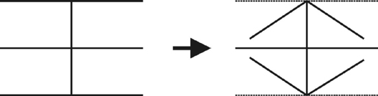
The resulting antenna can be built using wire elements strung on a supporting cross, which makes it possible to use lightweight materials like fiberglass and wire. Bending the element ends towards each other has the additional benefit of
enhanced coupling between the elements ("capacitive/inductive end coupling"), which in turn seems to enhance the F/B ratio and antenna operating bandwidth.
Dick Bird, G4ZU was the first one who had the idea of bending the elements like this, and named it the
"Bow-and-Arrow Yagi" or
"Bird-Yagi". As far as I know he only developed
monoband yagis of this shape.
[back to top]The spider beam is a
multiband design. Three monoband "bow-and-arrow yagis" are interlaced on the same supporting cross:
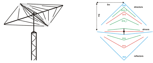
With such a design, several challenges mut be met:
1. Minimal interaction: This is the biggest challenge with any multiband antenna: we need to find a design where the
interaction between the monobanders is minimal. After endless NEC computer modeling and testing runs, the final spider beam dimensions evolved. They have negligible interaction, resulting in near-monoband performance on each band.
2. Uncritical design: Special attention has been paid to come up with a forgiving design. The
spacing of the wire elements is
not critical, which is quite an important point: this antenna will not only have good performance in the ideal world of a computer model. It will also perform equally well in real life (where it may bend and flex in high winds) - even when it is put up "quick and dirty" on a DXpedition (where nobody has time to tune and prune a critical system). The Spiderbeam users only need to pay attention during the very first set-up, to make sure the wire elements are cut exactly to the given dimensions. Once this job is completed carefully, the antenna will always perform well, and the repeatability is very good.
3. Feeding system: Another challenge with most multiband antennas is the feeding system. A very simple and robust solution could be found here. The 3 driven elements are 3 separate dipoles that are all tied together in one common feedpoint. The trick is to space the dipole centers apart and use short pieces of symmetric transmission line to interconnect them. This minimizes the interaction and results in a very forgiving and
broadband, low loss multiband dipole. The feed point impedance is 50 Ω, fed directly through a W1JR type current choke balun. No phasing lines or lossy matching devices to worry about. A
single coax cable can be used for feeding up to 5 bands without problem.
4. Corrosion protection: The driven elements and short pieces of symmetric feedline are manufactured in once piece, leaving no electrical joints open for corrosion. The same is true for all reflector and director wire elements.
All active parts of the antenna are protected by a very tough PE coating, protecting them against the environment for many years. There simply are
no corrosion problems with such a wire antenna! This is a huge benefit over aluminium antennas (especially if traps are involved), whose performance can suffer greatly once corrosion starts to set in.
5. Mechanical Strength: The fiberglass tubes will take a lot of beating, since they are
very flexible. The antenna will flex in the wind but it will not break. Remember a strong and flexible material will often outlive a brittle and rigid material. This is especially true for the reinforced fiberglass tubes which are used in the heavy duty version - these are very strong tubes but still highly flexible.
Another trick is the extensive guying with Kevlar lines.
Each spreader is guyed 4 times (up/down/left/right) - a concept very well known from sailboat masts. Of course all other parts used in the kit are UV ray and weather resistant.
For the wire elements, we use top quality "CQ-532" wire from the Wireman in our antenna kits, and recommend it to all homebrew users as well.
This wire will not stretch at all, which is really important. Otherwhise the resonant frequencies of the parasitic elements may change, and the good antenna performance is lost.
6. Optimized for portable operation: The mechanical construction was carefully optimized for portable installation on lightweight push-up masts. The special mounting plate ensures that the mast goes
right through the antenna center of gravity, instead of putting the antenna on the side of the mast. Antenna weight and vertical torque momentum are optimally distributed on the mast and rotator, greatly reducing the load on these parts and making extending or retracting the push-up mast much easier. A great
variety of mast diameters can be used (30-60mm) and
nearly no tools are necessary (only two #10 spanners). The spreaders are made from
20 identical fiberglass tube segments - introducing some redundance and greatly improving repeatability when compared to telescopic tubing. The wire elements and balun are mounted with
Velcro straps - a very quick and surprisingly strong method, at the same time maintaining the antenna's flexibility - and even serving as a nice and soft stress relief device. (In the heavy heavy duty permanent version, the Velcro is replaced by V2A clamps with a rubber padding).
CONCLUSION:
The spider beam is a
trapless multiband yagi constructed of 3 interlaced monobanders, making it a
highly efficient antenna and
simple construction. The driven element is a directly fed multiband dipole, again contributing
to a simple, broadband and low-loss construction. The design is very
forgiving, provided the wire elements were cut exactly in the beginning and high quality (non-stretch) wire is used. The mechanical design is optimized for
quick, lightweight portable installations, using high quality materials for good
reproduceability and a
long life without performance degradation.
[back to top]Compare the diagrams and tables in the technical data section. You will find that the spider beam is always
equivalent or better than a big conventional tribander with about 7-8m (25ft) boom length. Especially the
operating bandwidth is much better than with trap designs:
- forward gain is about 5dBd (7dBi) in free space (= 12dBi in 10m height above ground) and stays nearly constant over the whole band(s)
- F/B ratio is about 20dB or better on all bands
- SWR stays below 1:2 on all bands
On-the-air comparisons and measurements confirm these results.
Only a true 3 element
monobander will still be a little bit better: it has the same F/B ratio and pattern and 6dBd (free space) gain. Unfortunately some manufacturers still claim much higher gain numbers, even for their multiband antennas, which simply is not true.
An interesting feature is the flexibility to quickly optimize the spider beam for the CW or SSB band section.
The basic spider beam dimensions are designed to cover the whole band. If you want to operate CW or SSB only, simply change the wire lengths slightly to shift the optimum pattern into your desired frequency range.
[back to top]
4. Similar Antenna designs
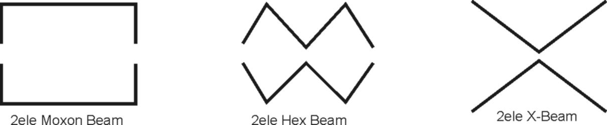
Over the years people have used their imagination to bend the elements in various shapes. No magic envolved here either. Two well-known examples for
2-element yagis with bent elements are the
Moxon rectangle and the
Hexbeam. These designs also benefit from the enhanced coupling caused by bending the element ends towards each other ("capacitive/inductive end coupling").They can be built from fiberglass and wire in a similar fashion, resulting in the performance of a well-designed 2-element yagi.Another example that looks similar is the
X-Beam, although I found its performance to be less than a 2-element yagi.
 [back to top]
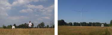
 5. Antenna Measurements and Tests
The development process of the antenna involved countless NEC simulations, followed by tests & measurements on the real antenna. During that test phase the antenna was put up at 10m height on an open field and has been measured intensively. The velocity of the wire we use ("CQ-532" from
The Wireman) had to be determined exactly, and the lengths derived from the computer model were adjusted accordingly. End effects by the insulators had to be taken into account. After applying these
corrections the
pattern diagram of the antenna (put up at 10m height) was measured on all bands, in
steps of 100kHz. The shareware „Polar-Plot“ by
G4HFQ is a very suitable tool for this job. A very good match of the computer predicted values and the measurements could be found.
In August 2003 I made some comparison measurements between two spiderbeams with different feed systems. The two antennas were installed side by side on the test field. After concluding these measurements I converted one of the beams into a simple rotary dipole and took a long series of measurements, thus comparing the gain of the spiderbeam to a dipole at exactly the same height. Again, a very good match to the computer predicted values could be found.
(
Click on the picture to read more about the gain measurements and see an enlarged view)
 [back to top]
6. Spiderbeam Evolution
-
Spiderbeam Version 0
(1998 - 2002: computer simulation and first prototypes)
-
Spiderbeam Version 1.0
(2003: old feeding system (somewhat critical), complicated assembly (stiff wire and epoxy insulators), repeatability and assembly time not optimized)
-
Spiderbeam Version 2.0
(2004: new & improved feeding system (very uncritical, forgiving and broad-band) and revised mechanical design (new: fiberglass tube segments, insulators, Velcro quick assembly, flexible CQ-532 wire, new balun) resulting in great overall improvements of user friendliness, repeatability and greatly reduced assembly time)
-
Spiderbeam Version 2.2 (2005: current version, further mechanical enhancements, addition of heavy duty version for permanent installation)
[back to top]
7. Thanks
Many thanks to W9XR for putting me on the trail of the "Bow-and-Arrow Yagi", and everybody who helped during the development phase - especially DF4RD, DF9GR, DJ6LE, DL6LAU, HA1AG, HB9ABX, W4RNL, WA4VZQ. Also to everybody who helped translating the constructionguide to other languages: 7X5AV, 9A2EU, 9A2NO, 9A6C, BG7IGG, CT1IUA, CT3EE, EA2PA, F2LZ, F4ANJ, F5IJT, F6IIE, G3MRC, G3SHF (& Team), HA8SLT, HB9ABX, I0SKK, IZ5DIY, JA1KJW, LX2AJ, LZ2STO, OH1RX, OH6NT, OK1DMU, OK1FIM, OZ8A, PA1TT, PB0P, PE2RID, S51TA, S57XX, SM0ETT, SM0JZT, SP8SW, SV2KBS, SV8YM, RA3TT, RV3DA, UA3ZTZ, YC0CRA, YO5QCD, YU1QT. Thanks for the incredible worldwide support and great response - without it this whole project would never have come so far.
Kudos to Dick Bird G4ZU who came up with the original "Bow-and-Arrow" idea, which lead to the whole Spiderbeam development. Unfortunately I never met him in person before it was too late.
R.I.P. OM.